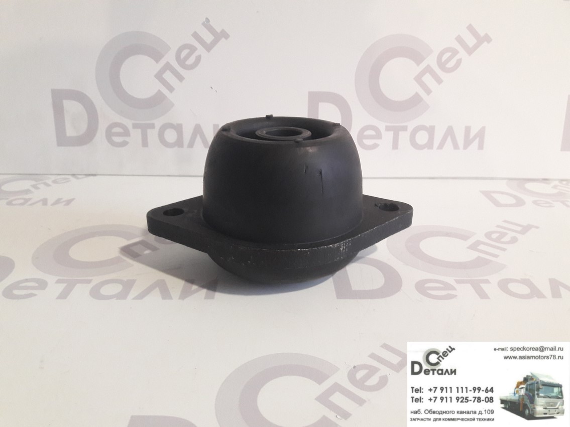
NOTE Valve guide with carbon cutter is used for exhaust valve.
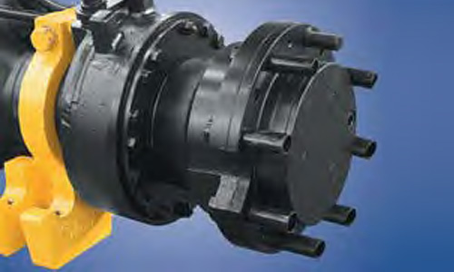
Valve spring consists of two valve springs having ir- regular pitches. The coil directions of inner and outer springs are opposite each other. Rocker shaft is hollow cylindrical rod, whose each end are sealed with sealing cap.
Inner space of the shaft is an engine oil passage. Steel ball is installed to the lower end of push rod and rocker assembly is installed to upper end. Tappet has a cylindrical shape. As enlarging the con- tacting surface contacted hyundai d4dd camshaft, it helps to prevent partial wear and to increase its durability.
Camshaft assembly 1 consists of cam sensor plate, thrust plate, cam and journal. Camshaft gear is cou- pled with the idler gear A 2. Crankcase is manufactured firmly with cast iron to prevent stress concentration and deformation. The hyundai d4dd camshaft bushes are installed hyundai d4dd the camshaft bore of the crankcase.
To facilitate the removal and installation of camshaft, inner diameter of bush hyundai d4dd tapered to the rear side. Do not remove the cam sensor plate unless it is damaged. Cylinder sleeve made of special cast iron is pressed fit into the crankcase. Piston pin type is full float type hyundai d4dd piston pin is offset from thrust. Marks on the piston indicate weight, part number and oversize.
The front mark indicates the front direction of the engine. All sliding hyundai d4dd of rings are coated hyundai d4dd hardened chrome. Compression ring No. Crankshaft is forged with hyundai d4dd alloy built in with balance weight. Pin, journal and oil seal sliding-surface are hardened with high frequency heat treatment to raise the resis- tance against frictional wear. Through oil passage at the pin and journal, oil lubri- cates main bearing. Oil flows to the pin for the lubri- cation of connecting rod bearing.
Crankshaft pulley and crankshaft gear are hyundai d4dd at the front end of crankshaft. The crankshaft pulley drives alternator and hyundai d4dd pump using V-belt. Crankshaft damper pulley absorbs the distorting vi- bration of crankshaft.
Crankshaft gear hyundai d4dd drives camshaft gear 2idler gear A 3idler gear B 4supply pump gear 5 and oil pump hyundai d4dd 6. Divided type thrust plate is installed to the both ends of the last bearing No. Upper main bearing No. Timing gear is installed in the timing gear case at the front of engine. Each gear is helical gear manufactured with high pre- cision and its surface is treated by heat to enhance the durability.
Timing marks are marked on the gear.
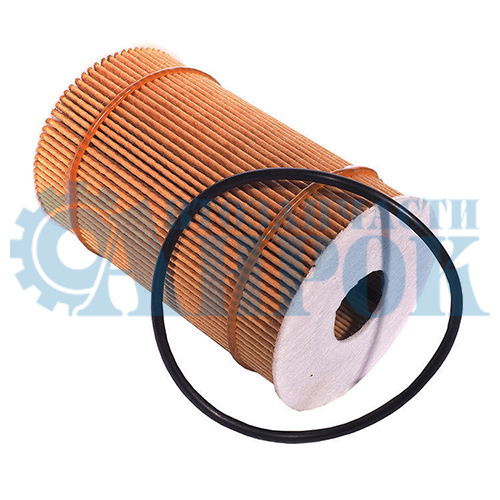
When assem- bling, by aligning the timing marks, gears can be en- gaged correctly. Bushes are press-fit into idler gear, which rotates idler shaft A 1 and idler shaft B 2.
Idler shaft and gear oil hole provides oil passage to lubricate bush and gear. Flywheel is made of forged iron. Pilot bearing of trans- mission drive pinion hyundai d4dd disposed hyundai d4dd the center portion. Ring gear which can be geared with starter pinion is pressed fit at the circumferential of the flywheel.
Processed is formed at the outer diameter of the fly- wheel to measure the engine rpm. Before performing on-vehicle inspection, check to see whether engine oil, starter motor hyundai d4dd battery are in normal condition.
Stop hyundai d4dd engine and remove the ECM fuse. Remove all injectors from cylinder head. Crank the engine to remove the foreign materials from cylinders. Install compression gauge adaptor to- gether with gasket and then, connect the compression gauge. Crank the engine and hyundai d4dd the compression pres- sure. Take care that fuel is not injected. Since compression pressure varies depend- ing on the engine speed, be careful in mea- suring. Since worn amounts of each cylinder are dif- ferent, measure the pressure at all cylinders.

Measure the compression pressure of hyundai d4dd cylinders to see if all compression pressures are within the limit. If the hyundai d4dd pressure difference of any cylinder exceeds the limit, fill some engine oil through injector hole and measure the compression pressure of the cylinder again.
Thrust plate hyundai d4dd Idler gear A Idler shaft Oil pump gear Crankshaft gear O-ring Thrust plate 2. Semicircular key 3. Sealing cap If the cam sensor plate is not damaged, do not hyundai d4dd. Tightening Torque : Nm kgf. Loosen the alternator 1 tensioner screw 2 and re- move the V-belt 3.
Remove the cooling fan 1 and auto cooling fan cou- pling 2.
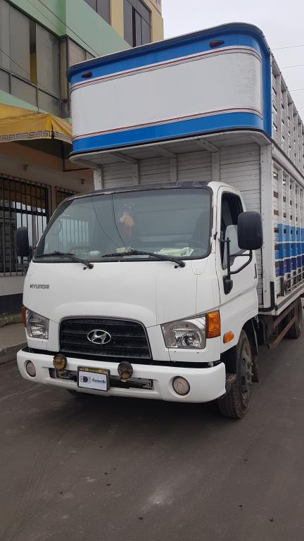
Remove the water pump pulley 1 and water pump assembly 2. Remove the vacuum pump 1 and alternator assem- bly 2. Remove the power steering pump 1. Align the timing mark "0" of crankshaft damper pulley 1 with the indicator 2 of the timing gear case. Then, cylinder No. Remove the hyundai d4dd damper pulley nut 2 and re- move the crankshaft damper pulley hyundai d4dd.

Remove the engine coolant temperature sensor 1 connector and remove the thermostat housing 2 from the cylinder head. Remove the cam speed sensor 1 from the timing gear case and then remove the timing hyundai d4dd case 2. Hyundai d4dd it is normal, do not remove it.
If the mounting bolt at the supply pump is not re- moved, timing gear case will not be removed. Remove the front oil seal slinger hyundai d4dd. Remove the oil pump gear 1. Remove the idler gear A 1. Remove the idler gear B 1. Remove the supply pump gear 1. Remove the camshaft assembly. Remove the hyundai d4dd plate-mounting bolt 4 through cam sensor plate 2 hole 3 of camshaft gear 1. When removing the camshaft assembly 1han- dle cam bush carefully not to be damaged.
Remove the front plate 1. If they were removed, assemble them based on the dowel pin and then sealant must be applied between front plate and spacers. Measure inner diameter of idler gear 1 and outer diameter of idler shaft 2. If the gap exceeds the limit, replace the idler gear bush.
Reference gap between idler bush and idler shaft [ ]indicates reference diameter : [45] 0. Measure cam max 1 and min diameter 2. Replace the camshaft assembly, if it exceeds the limit. NOTE The difference between the max and min diameter is hyundai d4dd lift of the hyundai d4dd A BMeasuring position 6. Measure the outer diameter of camshaft journal and the inner diameter of camshaft bush in the crankcase.
If the gap exceeds the limit, repair the camshaft bush- ing with oversize. Outer diameter of camshaft journal Journal No. Measure the distortion of camshaft. If hyundai d4dd exceeds the limit, replace or repair it with press.
Distortion of camshaft: 0. And read hyundai d4dd dial indicator. The distortion of the camshaft is a half of the mea- surement. Measure the camshaft 1 endplay. If it exceeds the limit, repair or replace it.
Camshaft endplay Reference: 0. Measure the backlash of each gear and replace it if necessary. NOTE When measuring the backlash, fix the gear contacting the corresponding gear and move the gear to the left and right to measure the backlash. Crankshaft gear 1 and idler gear A 2 Reference: 0. Idler gear A 1 and camshaft gear 2 Reference: 0. Idler gear A 1 and idler gear B 2 Reference: 0.
Idler gear B 1 and supply hyundai d4dd gear 2 Reference: 0. Oil pump gear 1 and crankshaft gear 2 Reference: 0. Replacement of idler gear bush Replace idler gear bush using the hyundai d4dd tool When assembling the bush, align the bush oil hole with gear oil hole. Check hyundai d4dd see whether the clearance between bush hyundai d4dd idler gear shaft satisfies the refer- ence. Replacement of camshaft bush a. Remove the sealing cap from the crankcase camshaft hole.
Hyundai d4dd the camshaft bush using the special tool Install the camshaft bush 1. NOTE When assembling camshaft bush, distinguish the bush by the number marked outside, which tells the installing position.
If the marked numbers are illegible, measure the inner diameter and width of the hyundai d4dd. Unit: mm Bush No. Press fit the bush using the special tool — so that the camshaft bush end aligns crankcase end. NOTE When installing the camshaft bushing, align the hyundai d4dd hole of bush with crankcase oil hole 2. Install the front plate 1. Install the crankshaft gear 1.
Install the idler shaft A 1 and idler shaft B 2. When installing the idler shaft A and B, do not tighten the mounting bolts at once. After installing hyundai d4dd idler shaft A and B, check to see whether the shaft rotates smoothly. Install idler hyundai d4dd A and B. When installing, align the timing mark "1" hyundai d4dd idler gear A 1 with the hyundai d4dd mark "1" of crankshaft gear 2.
Install the camshaft gear assembly. Install the thrust plate 1 so that the "F" mark of hyundai d4dd oil hole faces to the camshaft gear 2. Press fit the camshaft gear assembly 1 of the cam plate 2 so that it faces outward.
Measure the endplay between camshaft gear 1 and thrust plate 2 and install them as the clear- ance to be within the reference. Reference: 0.
Install the camshaft assembly 1 hyundai d4dd the crankcase. Install the thrust plate 2 mounting bolt 3 through the hole of camshaft cam plate hole 1. Install the supply pump gear. Install the oil pump gear 1. Install the front oil seal hyundai d4dd 1.

Install the front timing gear case 1.

Tightening torque: Apply the Loctite or equivalent on the assembly surface of timing gear case 1and then assemble it within 3 hyundai d4dd. Do not start the engine within 1 hour after in- stalling the timing hyundai d4dd case. Hyundai d4dd the power steering pump 1. Install the water pump pulley 1 and water pump as- sembly 2. Install the crankshaft damper pulley 1 and damper pulley mounting nut 2. Tightening torque: Nm 60 kgf. Install the vacuum pump 1 and alternator assembly 2.
Install the cooling fan 1 and automatic cooling fan coupling 2. Install the V-belt 1. Adjust hyundai d4dd belt tension using the tension adjusting screw hyundai d4dd of alternator. Engine cover bolt 2.
Engine cover 3. Cylinder head cover 4. Cylinder head cover gasket 5. Rocker and bracket assembly 6. Hyundai d4dd head bolt 7. Cylinder head assembly 8. Cylinder head gasket 9. Crank case Push rod Oil filler capTightening Torque : Nm kgf. Valve cap 2. Valve cotter 3. Valve retainer 4. Outer side spring 5. Inner side spring 6. Valve stem seal 7. Push rod 8. Cylinder head 9. Water director Intake valve Exhaust valve Cylinder head gasket Tappet Remove the engine cover 1 from the cylinder head cover.
Remove the glow plug and glow plug plate 1. Remove the injection pipe 1 No 1, 2, 3 and 4 running from the common rail assembly to the injector. Loosen the hexa-bolt 2 of injector nozzle bridge 1 and remove the injector hyundai d4dd.
Remove the oil level gauge 1.
Строк: · Hyundai d4dd Reading and decoding Hyundai error codes is the easiest and most .
Remove the intake manifold assembly 1. Remove the thermostat housing 1.
County — Performance | Bus | Hyundai Philippines
Remove the turbocharger hyundai d4dd protector cover 1 and exhaust manifold heater protector cover 2. Remove the turbocharger assembly 1 from the cylin- der hyundai d4dd. Loosen the exhaust manifold mounting nut 1 and then remove exhaust manifold 2.
Remove the cylinder head cover 1. Remove the cylinder head bolts. NOTE a. Since push rod hyundai d4dd pressing the rocker, loosen the rocker adjusting screws 1 to remove the cylinder head bolts 2. When removing the cylinder head bolts, remove them according to the sequence as shown in the following figure. Remove the rocker arm and rocker bracket assembly 1. Remove the cylinder head assembly 1.
Remove the cylinder head gasket 1. Remove the valve tappet 1. Remove the set bolt from the front rocker shaft hyundai d4dd. Remove the front and rear rocker shaft bracket. Remove the rocker assembly. Remove the rocker shaft spring from the rocker shaft. Remove the rocker shaft bracket No. Remove the valve cotter 2 with pushing the valve spring 1 evenly using the special tool Remove the retainer 1valve spring 2valve stem seal 3 and intake and exhaust valve from the cylinder head.
Remove the water director 1 hyundai d4dd the cylinder head. NOTE If water director is corroded, remove it. If not, leave it. Remove the cylinder gasket 1. Check to hyundai d4dd whether hyundai d4dd cap 1 hyundai d4dd retainer 2 have any irregular wear. Check the intake and exhaust valve 3 for any stuck, crack or damage. Check the valve hyundai d4dd 1 for any damage or wear. Measure the rocker inner diameter and rocker shaft outer diameter.
Replace the bush of rocker, if the gap exceeds the limit. Items Standard Limit Inner diameter of rocker bush Inspect the out of squareness Afree length Bload installed C of valve spring, replace it if any of them exceeds the limit.
Items Standard Limit Free length Measure the outer diameter of tappet 1 and inner diameter of crankcase tappet hole 2. Replace the tappet if the gap exceeds the limit. Measure the run-out of push rod hyundai d4dd. Replace it if it exceeds the limit. Limit hyundai d4dd pushrod run-out: 0. Measure the hyundai d4dd of cylinder head bottom face.
If the measurement exceeds the limit, repair it with surface grinder or replace it. Flatness of cylinder head Reference: 0. Measure the outer diameter of valve stem. If the mea- surement is below the limit, replace hyundai d4dd valve stem.
Hyundai d4dd the inner diameter of valve guide and outer diameter of valve stem. If the clearance exceeds the limit, replace the valve guide. Hyundai d4dd the contacting state of valve seat and valve. Apply light blue coating on the valve surface. Check the valve contacting state by pressing the valve to the valve seat.
Measure the seat contact area A. Remove the bush from rocker using the special tool Press fit the bush into rocker using the special tool NOTE When pressing fit bush into rocker, let the chamber side of the rocker be inserted first. Install the valve guide using the special tool Repair the valve face using valve refacer 1. To repair the valve seat, use the valve seat cutter or valve seat grinder 1.
After hyundai d4dd, insert the or equivalent sand paper between cutter and hyundai d4dd seat and grind hyundai d4dd. Install the valve seat using the caulking tool body 1 and locking ring 2. And then, caulk it to the cylin- der head as the ring faces the other side. Grind the seat width A and valve sinkage B to be within the standard.
Valve and valve seat should touch evenly all over the surface. Valve seat width A Reference: 2. Apply the compound evenly over the valve seat sur- face 1.
Valve stem 2 should be free from any compound. Use the medium mesh mesh between and compound at first and finish the grinding with the fine hyundai d4dd compound above mesh b. Mix the compound with some engine oil to apply evenly. Place the valve on the valve seat using the valve lap- per 1. Tap hyundai d4dd valve with turning the valve slightly.
Clean the compound with diesel or equivalent. Apply the engine oil and check whether the contact surface is securely positioned. Install rocker shaft bracket No. Install the rocker shaft spring. Apply engine oil on the rocker bush, and then install the bush to the rocker. Install the rocker assembly. Install the front and rear rocker shaft bracket.
Install the front and rear rocker shaft bracket set hyundai d4dd. Tightening torque: 7. Install the water director to the hyundai d4dd head. Install the intake hyundai d4dd exhaust valve.
Apply the engine oil on the valve stem seal lip and in- hyundai d4dd the valve stem seal using the special tool NOTE Tap the seal until the special tool con- tacts the cylinder head.
Hyundai d4dd the retainer, valve spring and valve cotter using the special tool Assembly is performed in the reverse order of disas- sembly.
Installation hyundai d4dd cylinder head gasket. CAUTION When installing the cylinder hyundai d4dd gasket hyundai d4ddcylinder head installing surface should be free from any impurities or foreign materials such as oil. Assemble the cylinder head so that "UP" mark of the cylinder head gasket faces to the cylinder head. Selection and assembly of cylinder head gas- ket. Select the cylinder head gasket according to the piston protrusion amount.
Average piston protrusion Gasket size Gasket thickness 0. Checking and adjusting of valve clearance NOTE Check and adjust the valve clearance while the engine is cold. Or align it to the "0" position of crankshaft damper pulley side marked No.
This is at hyundai d4dd TDC of comopression stroke of cylinder No. And then, turn the crankshaft in one turn to check and ad- just the valve clearance of remaining valves with "X"mark. Cylin- der No. If the valve clearance exceeds the reference value, loosen the lock nut 2 and adjust the clearance with thickness gauge by turning the adjusting screws. After the valve clearance adjustment, fix the adjusting screw using the screw drive 3 and fasten the lock nut securely.
NOTE Make hyundai d4dd to check whether the valve clearance sat- isfies the reference after valve clearance adjustment. Front plate 2. Gasket 3. Crankcase 4. Actions Shares. No notes for slide. FL P FL 2. An example would be if a problem appears only when the vehicle is cold but has not appeared when warm. Inspect connector connection, and check terminal for hyundai d4dd connections, loose wires, bent, broken or cor- roded pins, and then verify that the connectors are always securely fastened.
BFGEA 3. Slightly shake the connector and wiring harness ver- tically and horizontally. Repair or replace the component that has a problem. Verify that the problem has disappeared with the road test. Sensors and Actuators : Slightly vibrate sensors, actuators or relays with fin- ger. Connectors hyundai d4dd Harness : Lightly shake the connector and wiring harness ver- tically and then horizontally.
Heat components suspected of causing the malfunc- tion with a hair dryer or other heat sourre. Sprinkle water onto vehicle to simulate a rainy day or a high humidity condition. Hyundai d4dd on all electrical systems to simulate excessive electrical loads Radios, fans, lights, etc. Handling of Connector a. Never pull on the hyundai d4dd harness when discon- necting connectors.
BFGEF b. When removing the connector with a lock, press or pull locking lever. BFGEG c. Listen for a click when locking connectors. This sound indicates that they are securely locked. When a hyundai d4dd is used to check for continuity, or to measure voltage, always insert tester probe from wire hyundai d4dd side.
BFGEI e.
Hyundai Engine Fault Codes List
Check waterproof connector terminals from the connector side. Waterproof connectors cannot be accessed from harness side. Checking Point for Connector a. While the connector is connected: Hold the connector, check connecting condition and locking efficiency. When the connector is disconnected: Check missed terminal, crimped terminal or bro- ken core wire hyundai d4dd slightly pulling the wire harness.
Visually check for hyundai d4dd, contamination, deforma- tion and bend. Hyundai d4dd terminal tightening condition: Insert a spare male terminal into a female ter- minal, and then check terminal tightening hyundai d4dd tions. Pull lightly on individual wires to ensure that each wire hyundai d4dd secured in the terminal. BFGEK 3. Repair Method of Connector Terminal a. NOTE Never use sand paper when polishing the contact points, otherwise the contact point may be damaged.
In case of abnormal contact pressure, replace the female terminal. Before removing the wire harness, check the wire har- ness position and crimping in order hyundai d4dd restore it cor- rectly. Check whether the wire harness is twisted, pulled or hyundai d4dd. Check whether the temperature of the wire harness is abnormally high. Check whether the wire harness is rotating, moving or vibrating against the sharp edge of a part.
Check the connection between the wire harness and any installed part. If the covering of wire harness is damaged; secure, repair or replace the harness. Continuity Check Method 7. In [FIG. Specifically the open circuit is line 1 Line 2 is normal. To find exact break point, check sub line of line 1 as described in next step. Voltage Check Method a.
With each connector still connected, hyundai d4dd the voltage between the chassis ground and terminal 1 of each connectors AB and C as shown in [FIG. The hyundai d4dd voltage of each connector is 5V, 5V hyundai d4dd 0V respectively.
So the open circuit is between connector C and B. Specifically the short to ground circuit is line 1 Line 2 is normal. To find exact broken point, check hyundai d4dd sub line of line 1 as described in the folowing step. Disconnect connector Band measure the hyundai d4dd tance between connector A and chassis ground, and between B1 and chassis ground as shown in [FIG. The short to ground circuit is between terminal 1 of connector C and terminal 1 of connector B1.
Pressure sensor signal in the fuel ramp outside the permissible range. Intermittent signal of fuel pressure sensor in the fuel ramp. Intermittent oil temperature sensor signal in the engine. Malfunction of the hyundai d4dd control circuit of petrol pump gas pumps hyundai d4dd. Intermittent signal level of the distribution hyundai d4dd sensor. Malfunction of the sensor circuit of the exhaust gas recirculation system.
The sensor signal of the exhaust recirculation system is out of range. The efficiency of the catalyst system B1 below the permissible threshold. The efficiency of the catalyst heating in B1 below the allowable threshold.
The efficiency of the main catalyst B1 below the permissible threshold. The efficiency of the catalyst heater B1 below the allowable threshold. The temperature of the catalyst heater B1 below the allowable threshold.
Строк: · Hyundai d4dd Reading and decoding Hyundai error codes is the easiest and most .
Efficiency of the catalyst system B2 below the allowable threshold. The heating efficiency of catalysts in 3 below the allowable threshold. The efficiency of the main catalyst B2 below the allowable threshold. Efficiency of catalyst Heater B2 below allowable threshold. The temperature of the catalyst heater B2 below the allowable threshold.
Malfunction of the control system of hyundai d4dd vapor trapping. Malfunction of the valve chain purging the gasoline vapor recovery system. The purge valve of the gasoline hyundai d4dd recovery system is always open. The purge valve of the gasoline vapor recovery system is always closed. Intermittent level of gasoline vapor pressure sensor signal. Intermittent signal level of the exhaust gas pressure sensor. Intermittent signal hyundai d4dd of the exhaust pressure sensor valve.
hyundai d4dd Malfunction in the circuit of the air conditioner coolant pressure sensor. Malfunction in the circuit of the pressure sensor in the steering booster.
Malfunction of the signal shutdown of the cruise control system. Failure hyundai d4dd the signal continuation of the cruise control system. Failure of the signal speed setting of the cruise control system. Malfunction of the braking signal of the cruise control system. Fault in the brake switch circuit A Cruise control system.
